Airboat controlled with Bluetooth
This airboat is based on an Arduino pro mini, a JDY-08 module for the communication and controlled with an Android mobile app.
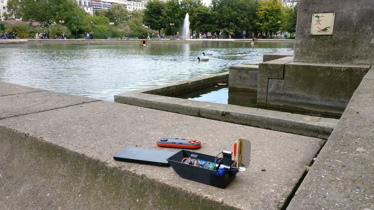
Near my flat, I have a little pond. Each day, I see that empty pond, and each day, I'm thinking about building a small boat. It's time to make it!

I don't have any submersible motor, so I will try to create an airboat with a drone motor.
Please note that I moved since I began this article... this pond is now at 500km from me).
Build in pictures
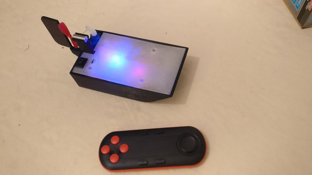
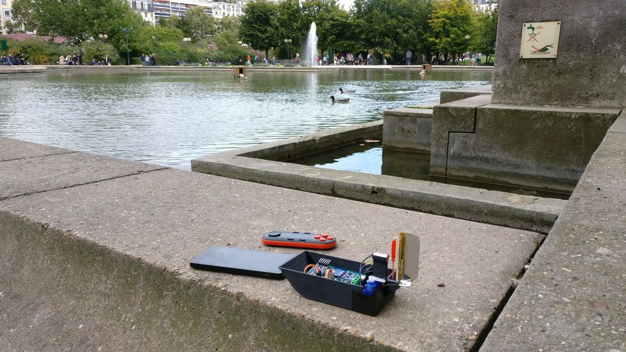
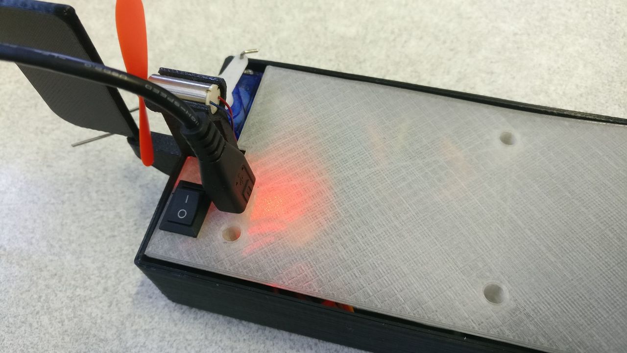
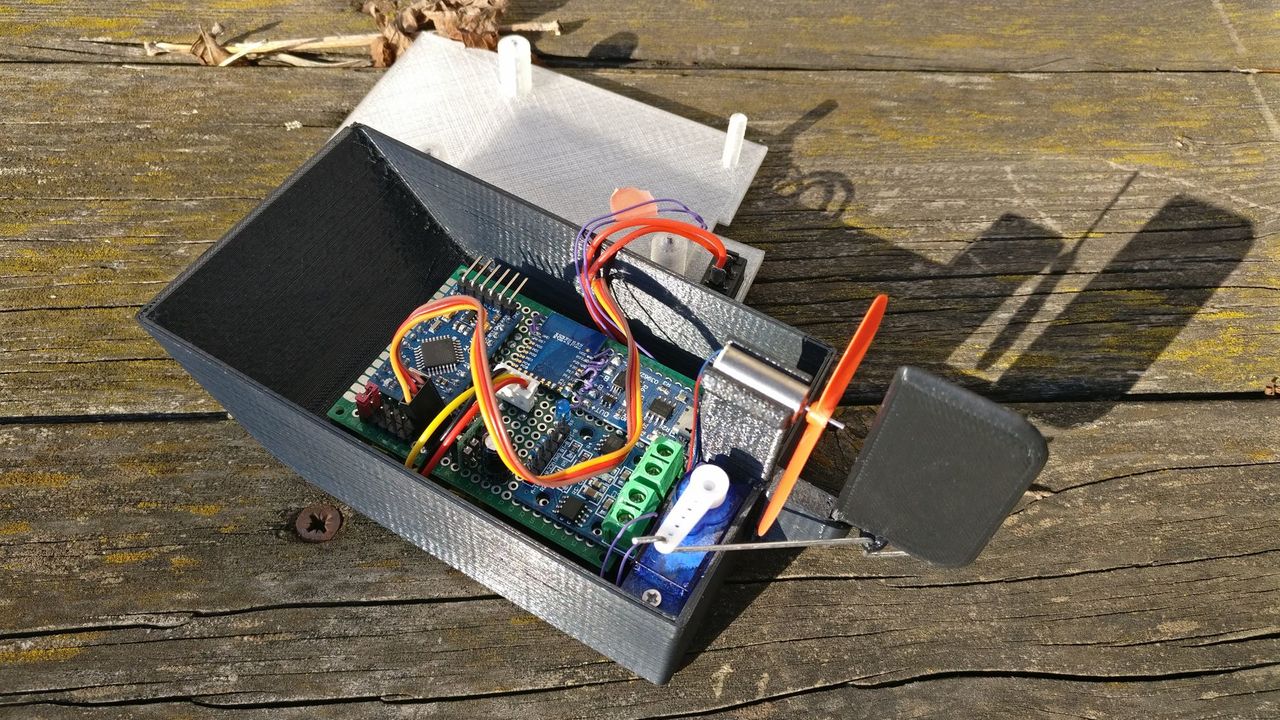
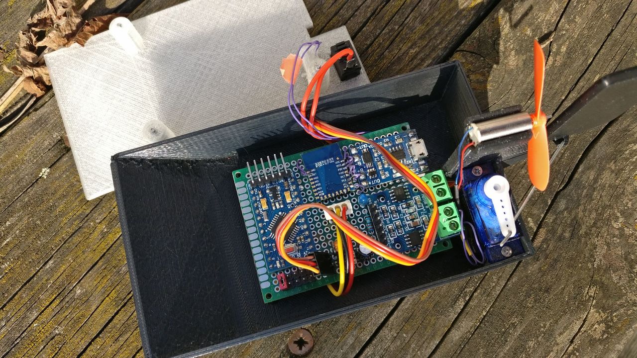
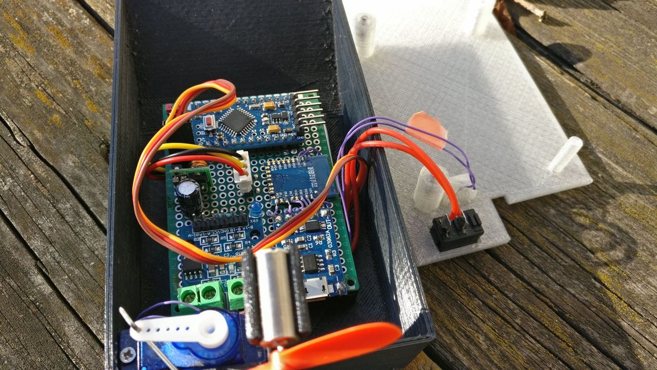
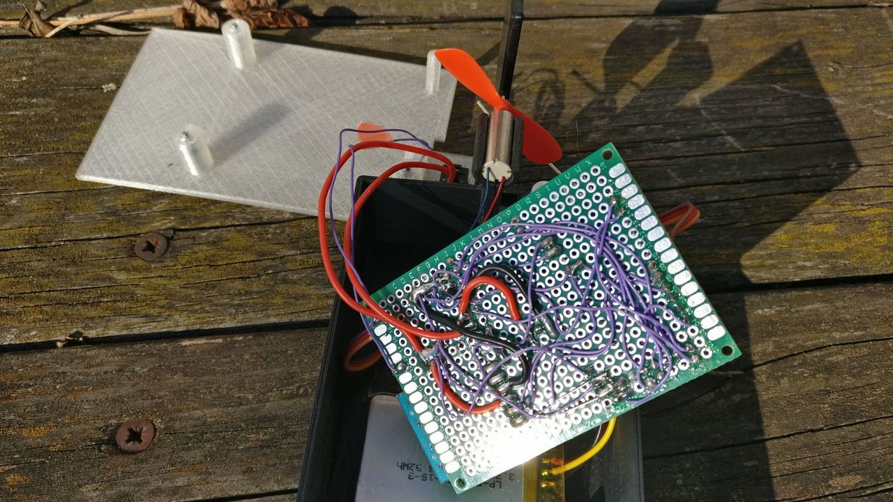
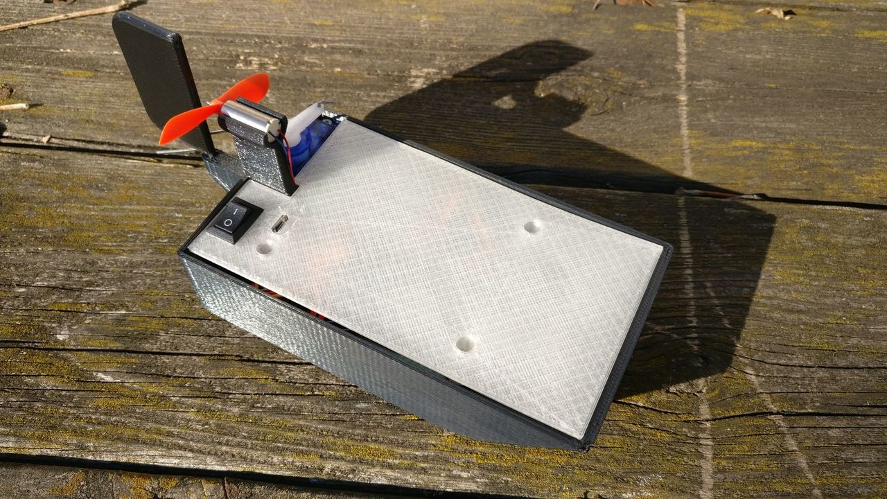
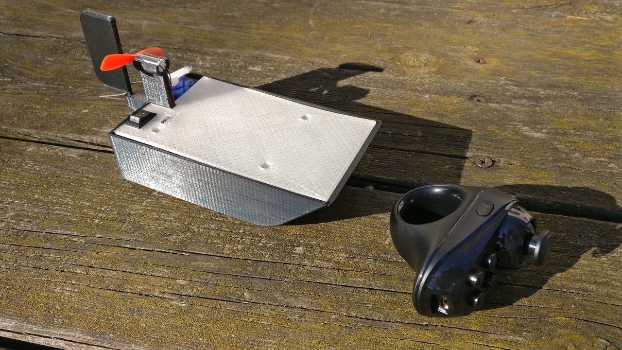
Big picture
My objective: create a small bluetooth controlled airboat. The airboat will be connected to a smartphone, as well as a small bluetooth controller ($5).
An android app will "translate" the commands of the controller to the airboat.

I will try to build a 3D printed boat, but the first iteraction could be made with foam.
Components
Power supply
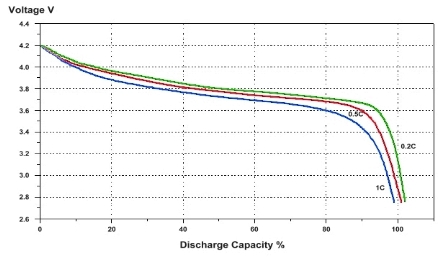
It will be battery powered, so the device will have to work between 4.2V and 3V (look at the discharge curve of li-ion batteries).
Gamepad
I will use this one:
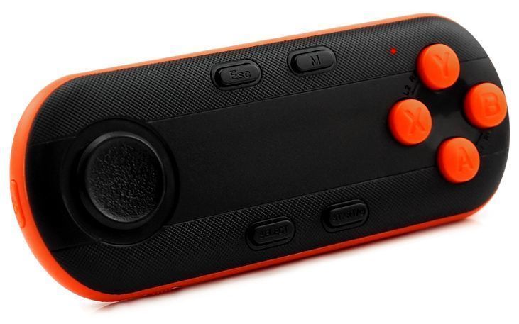
I'm not yet sure that it will work for my purposes, but by reading Android developper ressources, a controller seems to send some key event. It should be possible to catch them and to send some commands to the boat.
Bluetooth
I will use the JDY-08 flashed with a HM-10 firmware.
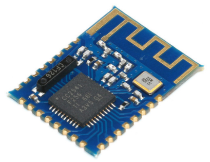
The CC2541 should be used between 2V and 3.6V, so I will need to add a DC step down regulator (in fact, I used the step down regulator of the Arduino Pro Mini - see below).
Once the connection established, the phone can send data over bluetooth (read/write a bluetooth service). If enabled, the phone can aslo send AT commands to the module.
Sadly, this module only have one PWM output, and it's not enough to control the motor to go straight and the motor to change the direction.
That's why I will have to use another MCU in addition to the bluetooth module.
Motors / Servos
Direction X
I bought a small DC motor used in quadcopter (7 * 16mm), working between 3.7V and 4.2V.
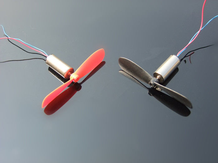
I powered one motor and mesured the power consumption. The motor use 800mA at 4.2V. A MCU cannot power this motor directly. I have to use an H bridge, cheap and compact.
At first, I wanted to use L293D chips, as they can manage 2A (and they are cheap). But they cannot work below 4.5V.
Then, I found a compact module (2.8cm * 2.1cm) based on the L9110 chip (around 0.50€). This IC can work with 800mA by channel (and has 2 channels), and can work between 2.5V and 12V.
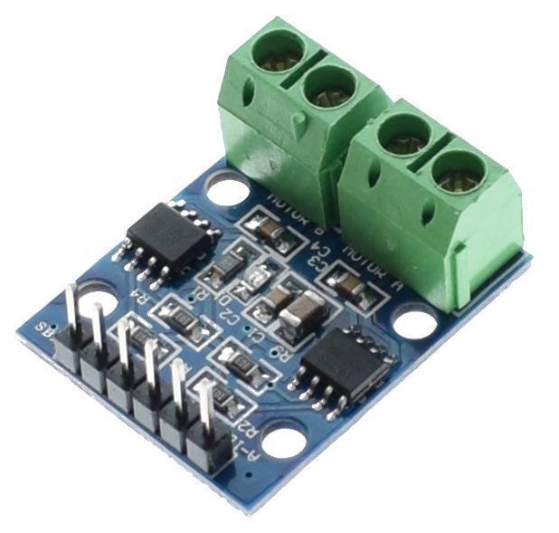
The DC motor will be directly powered by the battery, knowing that 3.7V will be reached at 80% of battery use.
Direction Y
For the direction on the Y axis, I will build something like a rudder to put behind the quadricopter, to influence the air flow.
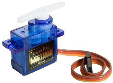
To move the rudder, I choosed to use a very common stepper motor, the SG90. It is cheap, and only weight 9g.
It works at 4.8V, so I will need a DC step up converter.
MCU
As the bluetooth module is powered at 3.3V, and the stepper motor and the L9110 chip can be controlled with 3.3V levels, I have to choose an MCU working at 3.3V. Moreover, I need a serial port, and at least 3 PWM outputs (2 for DC motor, 1 for the stepper).
I could use an ATtiny2313, but I want something simple, and this device doesn't have a lot of memory (using the "Serial" API is already too much).
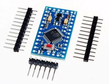
I will begin with an Arduino Pro Mini @ 3.3V.
DC Step up converter
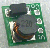
To get 5V for the DC stepper, I wanted to use a little module based on SX1308 or MT3608, but the Aliexpress version is quite big. I found something more compact:
This module will be used to power the stepper motor. But if the stepper works at 4.2V (instead of 5V), it will also power the quadricopter motor (to use the battery as much as possible, and avoid change of behavior when the tension decreases).
Sum up
- Power supply: Li-ion battery 3.7V (full 4.2V to empty 3V)
- Bluetooth module: JDY-08 (2V to 3.6V)
- Motors:
- X axis: Quadcopter DC motor (3.7V and 4.2V)
- Y axis: Stepper motor SG90 (4.8V)
- Motor driver: Module based on the L9110 chip
- MCU: Arduino Pro Mini 3.3V
- DC Step up converter
- Blue led (3mm) and resistor (around 25Ω)
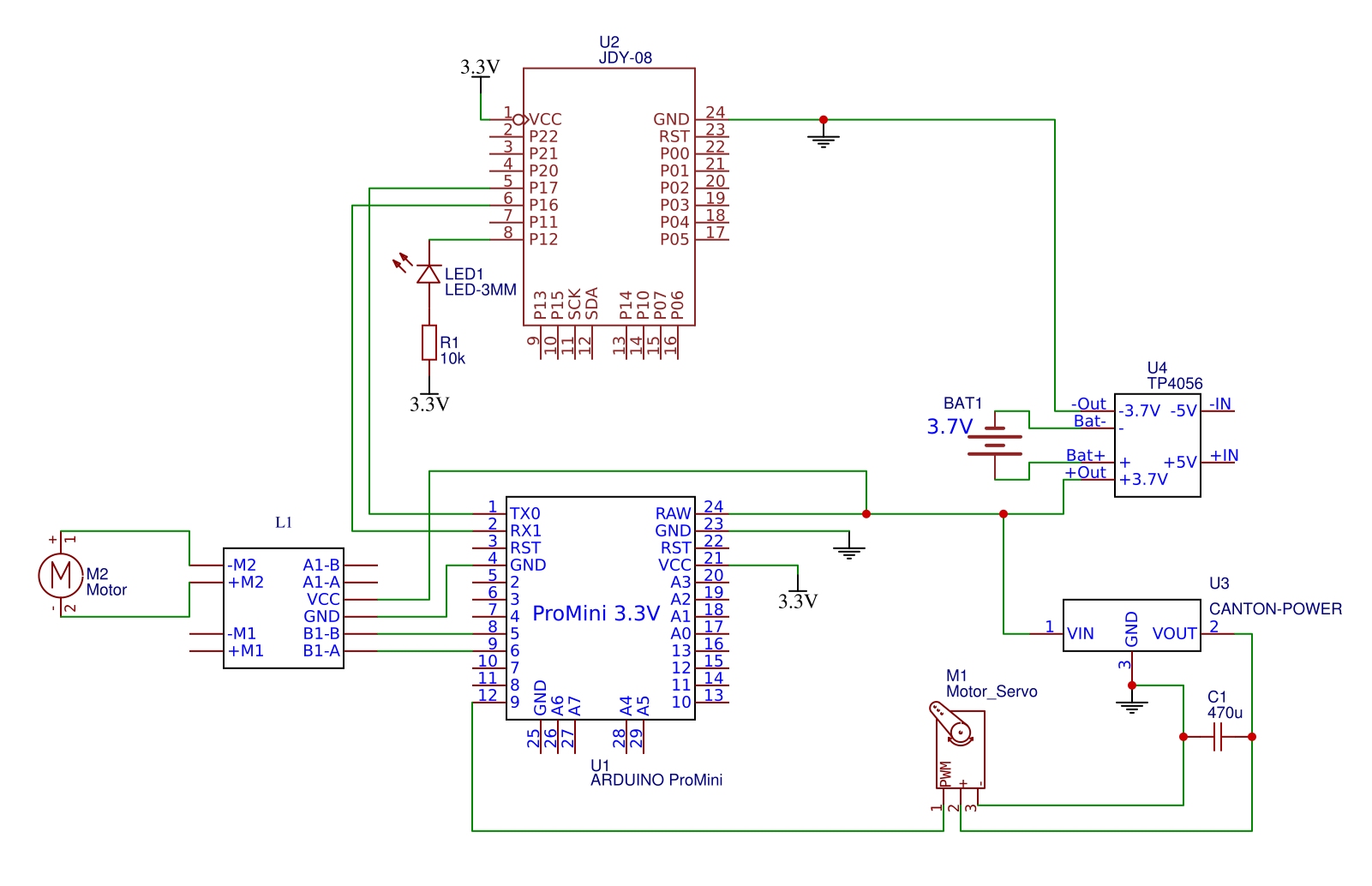
Circuit schematics
Bluetooth protocol
Once the connection established, the mobile app will have to send two informations:
- Throttle (-100 (backward) to 100 (full forward) - 0 for no throttle)
- Direction (left to right) (-100 to 100; 0 is the middle)
The mobile app will send thoses parameters with the following pattern:
AT$PARAMS:{throttle};{direction} followed by a carriage return.
Source code
Go to Github to download the source code.
Hardware and Software Serial
At first I wanted to use hardware serial for debuging, and software serial for controlling the BLE module.
Sadly, I learned that the Software Serial uses interrupts, and messes up with the servo timer which also uses interrupts.
Before realizing that, I added two capacitors (470µF between 5V and GND, and 10µF between Signal and GND) but I don't think it's necessary.
Serial.readline() and timeout
As the BLE HM-10 firmware doesn't use endline character, the call to Serial.readline() waits 1s before returning on timeout.
To avoid that, I changed the timeout of the serial interface to 50ms.
I didn't try less than that, but I'm sure it could be even better and still work.
Update: I finally changed the protocol to use the endline character to increase the responsiveness of the boat
Test with Android
Warning: you cannot connect to BLE devices before Android 4.3
- Download Serial Bluetooth Terminal
- Establish a connection with the JDY-08 module in Android settings
- The LED should stop blinking
- Launch the Serial Bluetooth Terminal app,
- Select the device (Menu > Bluetooth Devices)
- Go to "Menu > Terminal", and connect to the device with the little icon.
- Send a test command :
AT$TEST
Mobile App

The mobile app has two roles:
- Listen for key presses on the bluetooth controller
- Send the current state of each directions to the boat.
You can also download the source code on Github
The app is quite ugly but it works.
I changed a lot the mobile app to add some virtual joysticks.
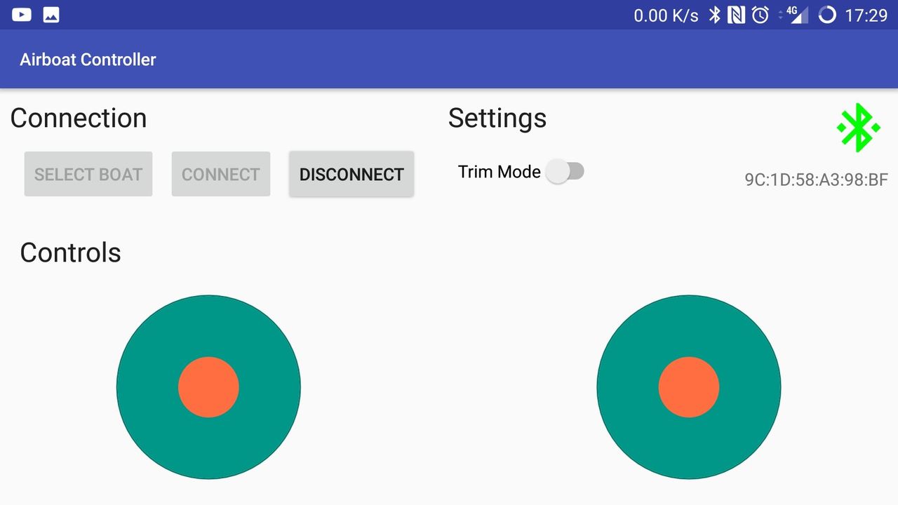
Please note that this app source code is really far from a production usage. It's just for fun ;)
Key mapping for the controller:
- Start: Connect / Disconnect
- Escape: stop motors
- Y: Trottle +10% or Trim Right
- X: Trottle -10% or Trim Left
- A: Set throttle at 10%
- B: Set throttle at 100%
- Select: Reverse throttle
- Joystick: Direction
Avoid sinking
I looked quickly how to be sure that my air boat will not sink.
The key to floating is that the object must displace an amount of water which is equal to its own weight. I have to be sure that the volume of air below the level of the water (big volume / light weight) compensate the weight of the boat itself (and its content).
For example, if my boat weigh 200g, it will move around 200ml of water (so around 200cm³). My boat should have more than 200cm³ of volume.
With my 3D print and fusion 360, I get:
- Volume of the boat: 160cm³
- Circuit weight: 60g
- Circuit volume: ?
- Boat weight: 35g
So, if the boat is well balanced (and it is NOT), it should be okay.
3D modeling
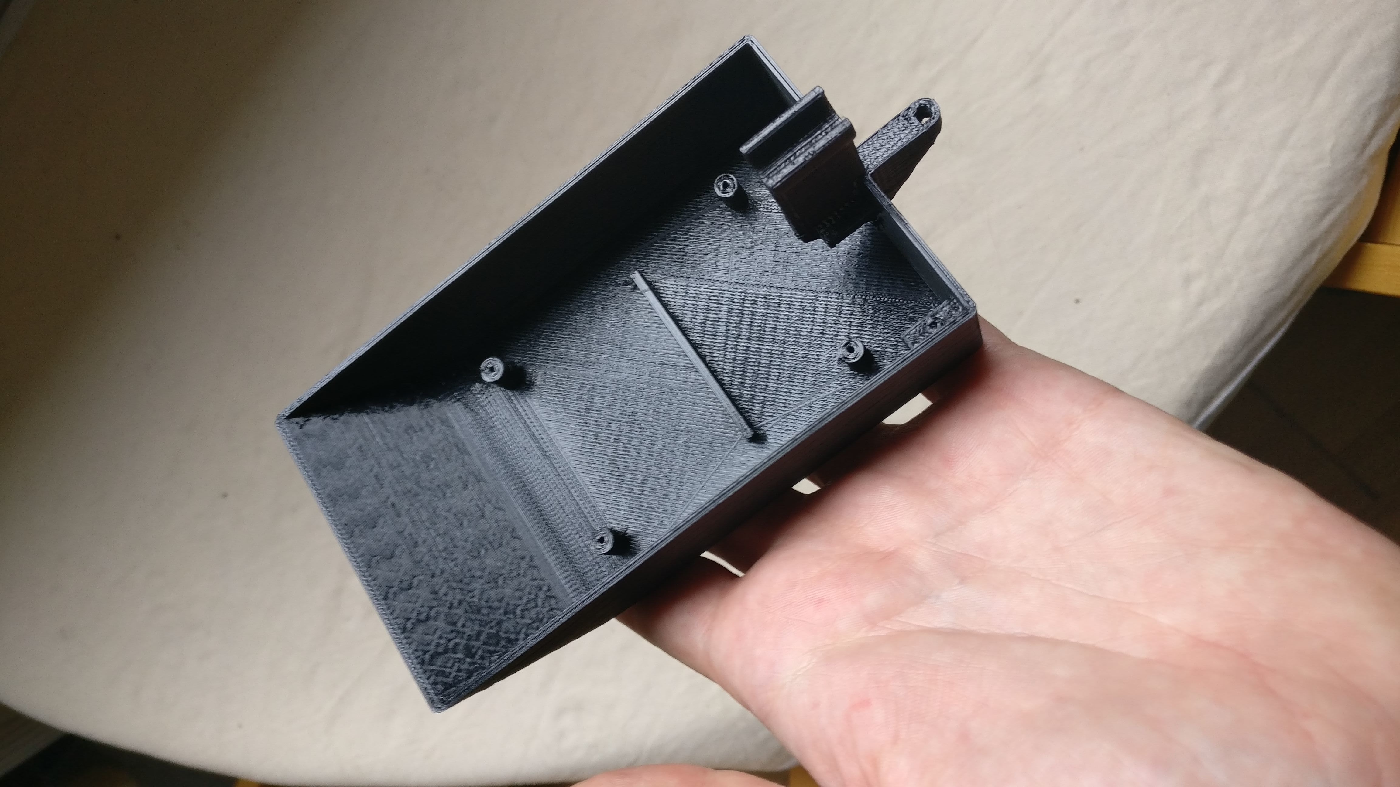
I created a small boat with Fusion360, with a translucent cover.
I know that the servo is really badly placed, but hey! that was not my first concern at the time :)
All parts can be printed without supports.
What's next?
The protocol I defined between the mobile app and the boat doesn't seems to be very efficient. It's something I need to work on - updated on the GitHub repo.
Moreover, the controller is very cheap, and the joystick is not precise enough to control the boat with precision - updated I added a virtual joystick on the mobile app.
I also think that the boat is too small and as the weight is not evenly distributed, it has an impact on the direction of the boat.
And of course, I know nothing about boats so it didn't hepled. But it was a fun project to work on!
